Environment Environment Environment
Condo-life and ham radio don’t typically mix well. With a few tricks, you can typically get a stealthy VHF/UHF antenna set up without much effort, but HF becomes problematic.
Maybe you’re lucky enough to have a tree which you can run a cable under your yard to and get a well-hidden end fed antenna, or perhaps you have an attic with enough room for an off-center-fed dipole. But what if you don’t? You might be tempted to put something on your Lanai or in a tight little area that will fit a whip antenna, but you’ll quickly find that concrete and walls do terrible things to your SWR.
Dense materials like concrete, metal, or even wood interact with antennas and change their electrical resonance. This can make it so that you’re antenna which was perfectly resonant in a field is way off-frequency in on your lanai, porch, or wherever else you’re trying to stick it.
Some variation is always to be expected, no matter where you place the antenna, but for expensive, compact antennas, or for whips that are perfect for portable use, you might not want to trim down its length to match its surroundings, and you might not be able to lengthen it!
Inverted V Dipoles
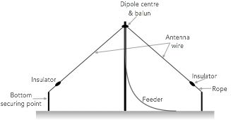
If you live in a house which you own, you might have considered what’s called an “inverted V dipole.” These antennas are long-wire dipoles sloped down to fit within tighter constraints.
These “inverted V dipoles” can work quite well despite typically cutting the gain a bit compared to a dipole in real-life scenarios, and if you have the room they are a great place to start.
If you have the room for one, I’d recommend it!
But, these antennas still take up quite a bit of room and require mounting points on each end of the antenna as well as at the top, making them an unlikely match for anyone that has to deal with anti-antenna HOAs or strict condo rules. Not only does it take up a lot of room, many HOAs require antennas to be self-supporting, which this one is not. However, there is one property of the inverted V dipole antenna that I want to focus on.
Some operators prefer inverted V dipoles over dipoles in certain areas, even if there is space for a dipole. Why would they purposely reduce the gain and efficiency of their antenna? It’s because that slope means that the antenna radiates neither horizontally nor vertically. Instead, it radiates at an angle. While the antenna’s radiation pattern is nearly identical to a dipole once you get out even a quarter of a mile, this style antenna can actually cut back on the interaction the antenna has with nearby objects.
Most pipes, wires, and support structures in houses and other structures will go either vertically or horizontally. These can restrict rf from effectively radiating, especially if they are near the resonance of the frequency you are transmitting on. While in most cases this restriction is negligeable, some operators have found significantly better results with inverted v dipoles due to this very mechanic.
“Great,” you’re saying to yourself. “If I ever move I can maybe use that knowledge, but where I live I could never get a dipole up, Inverted V or not.” Well, what if I told you that this trick could be scaled down and applied to your scenario? Here enters the upright V dipole!
The Upright V Dipole
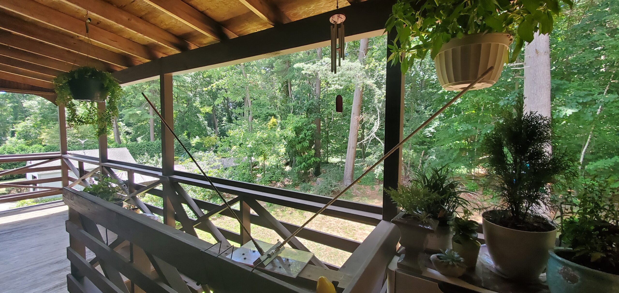
The “Upright V Dipole” takes the inverted V dipole, scales it down, and makes some interesting changes to it. Credit for this design to the the UH Ham Club of Hawaii. They had their own article on it back in ’99, but their site went down not too long ago. First comes the size change. Instead of longwire, the Inverted V uses mobile antenna whips mounted at an exactly 90 degree angle. Here’s a photo of one using 2 CB whips trimmed to be resonant on 10m:
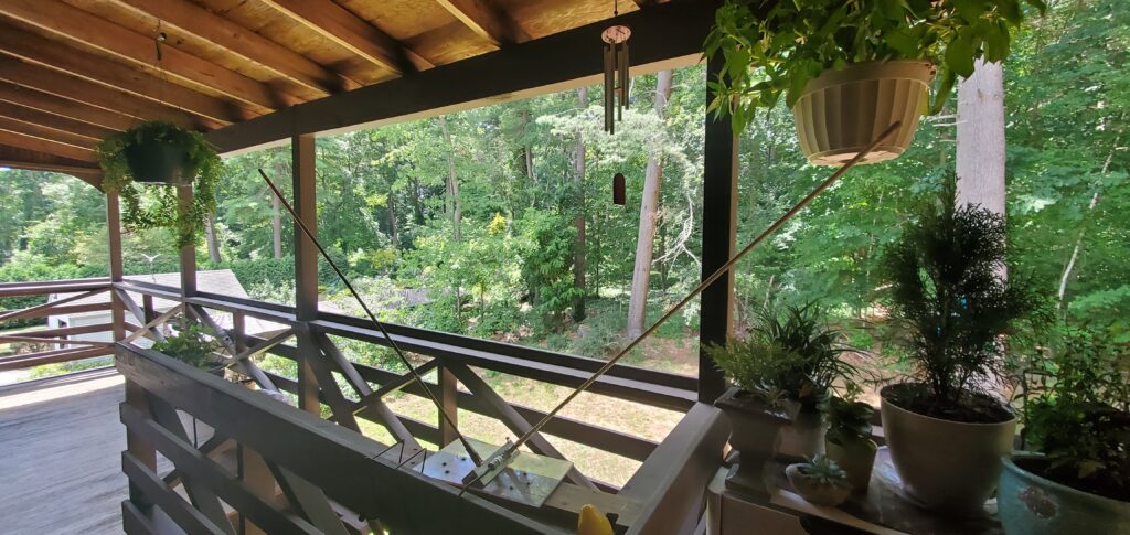
The upright V dipole flips the inverted V into, well, a V. While the strongest point of radiation is still near where the two parts meet, a lot more RF is radiated up instead of down into the ground.
The SWR was at 1:1 despite everything around it. I even moved it around in awkward positions and close to objects that cause frequent interference, but the SWR peaked up to 1.6 at the highest, except for when the antenna was physically touching a metal chair at which point it showed “infinite” on my nano VNA.
Now, that’s not necessarily a good thing. Antenna SWR will always change depending on the antenna’s environment. An antenna that proves more resilient to different environments typically proves to be more lossy an antenna, and this is no exception. My testing showed that a signal still gets out, so as always, the tradeoffs might be worth it in your case
Does it perform better than my End Fed Half Wave? No, but that’s to be expected. However, this antenna is more than serviceable. It did out-perform my single whip antenna on my car.
There are some things to note with this antenna. It is a compromise by design, but what you get for that compromise is stable SWR and great performance. Even with the reinforcing bars of a lanai, you can expect to get out a decent signal. It’s somewhat directional, especially for local contacts, but with it’s upwards facing radiation pattern, for DX it’s mostly omnidirectional. Height also really mattery for this antenna.
It’s useable on 6m, 10m, 15m, 17m, 20m, 30m, and 40m as long as you have whip antennas for whichever frequency you want to use. There are also multiband whips out there that work great for this! The useable area can be narrow on some of the bands, but swapping out antennas isn’t too difficult.
The biggest issue is height. The main reason why most operators would choose an inverted v antenna is because the point of the highest RF output is at the tip of the V. In an inverted v antenna, that’s the highest point, where on an upright v, that point is closer to the ground. Because of this, the higher you can get an upright V the better.
This means that while an upright v has a more ideal radiation pattern (facing upwards rather than downwards), the better height you can get with an inverted v often makes it still a better choice.
However, it can be much easier to mount temporarily, especially if your HOA requires it to be fully self-supporting. It’s also easier to put up and down, and it’s more resilient to environmental change.
Constructing the Upright V Dipole
The construction of the upright V dipole is fairly simple. The basics of it are that the two antennas should be 90 degrees from each other (right angle), and have the core of the BNC attached to one whip and the shield to another. Note that neither the shield nor the core of the BNC are attached to the metal bracket itself, and the Firestik K4R stud mounts are isolated from it.
Make sure that you get the K4R mount that has two O-ring isolators, as the mounts should be totally isolated from whatever they are attached to. These can be found on Amazon for around $12 each.
Here are some working links as of 2022:
- https://www.amazon.com/FireStik-K4-Antenna-Stud-Mounts/dp/B000X380KQ
- https://www.amazon.com/FireStik-Radio-Antenna-Heavy-Style/dp/B00T4PDV6C/
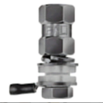
The BNC Connector will also need to be isolated:
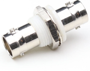
- https://www.amazon.com/ANHAN-bulkhead-Insulated-Connector-Straight/dp/B078MRDBPN/
- https://www.amazon.com/GDQLCNXB-Female-Bulkhead-Insulated-Connector/dp/B093SKPPPY/
Here’s a schematic to show its construction in more detail:
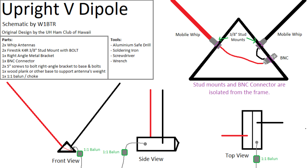
The 1:1 balun / choke is another important aspect of this antenna. It is used to isolate the second dipole element from the ground of the system. This greatly increases the efficiency of the antenna, reduces noise and interference in the antenna’s receive, and blocks rf from travelling down the coax back to the shack.
The balun must be added between the antenna and the coax leading to your read. The closer to the antenna the better. You might even be able to install the balun inside the antenna between the BNC connector and the two elements.
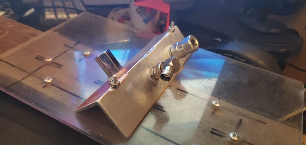
I recommend mounting the antennas on a metal right angle bracket, then attaching that to your base. Here’s one built by Russell KB1UKU:
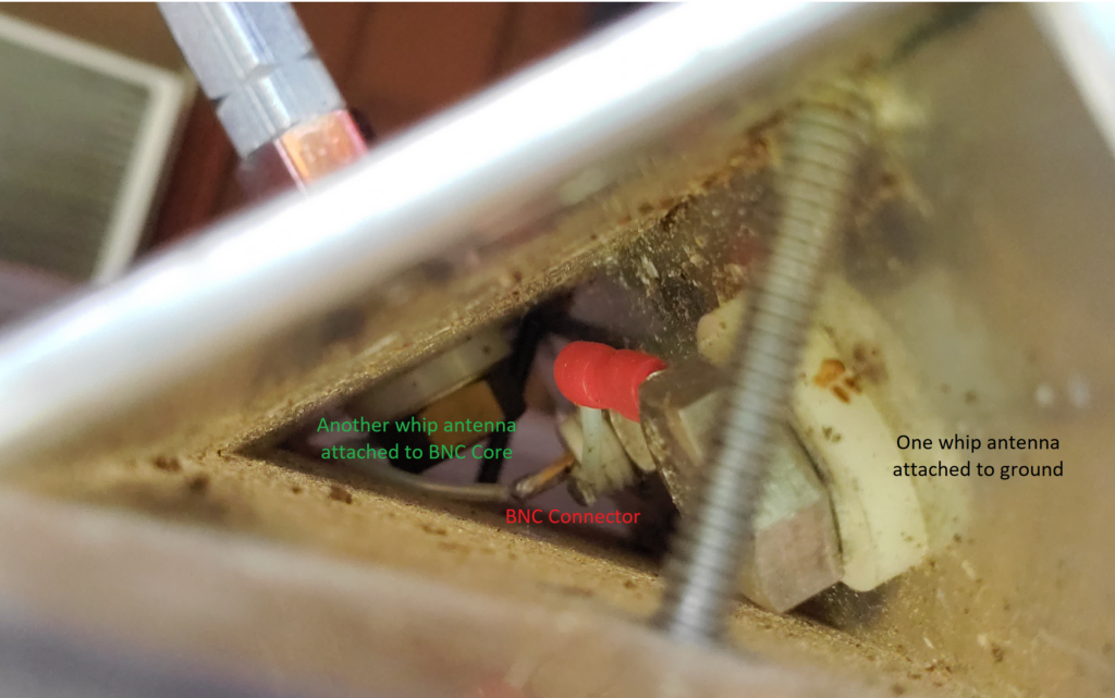
Excuse the dirt on the inside of the antenna from use and storage!
Conclusion
Overall, it’s an interesting antenna to be sure! Upon close inspection, it proves to be a fairly inefficient antenna, but anything is better than no antenna. If you think you can get away with a dipole, an inverted V dipole, or an end-fed, it’s better to start there in most cases. But, if you’re looking for a portable, SWR resilient, and easy to construct antenna, it may be an option worth considering.
Thanks for reading, and thank you to Russell KB1UKU for sharing the article with me and helping me learn about it!
No responses yet